- Both the methods are used to solve the complex network.
- Norton's Theorem & Thevenin's Theorem are "Duals".
- substitution theorem can be used in both linear and nonlinear circuits. For those nonlinear circuits that have a unique solution, we can use the substitution theorem in the equivalent transformation.
- they can be applied to both ac and dc source.
- For easy detemination of circuit parameter
Showing posts with label circuit network. Show all posts
Showing posts with label circuit network. Show all posts
Sunday, July 19, 2015
Application of network theorem

Conversion between thevienin circuit to norton circuit
A Norton equivalent circuit is related to the Thevenin equivalent by the following:


Thevenin's theorem
- Any linear electrical network with voltage and current sources and only resistances can be replaced at terminals A-B by an equivalent voltage source Vth in series connection with an equivalent resistance Rth.
- This equivalent voltage Vth is the voltage obtained at terminals A-B of the network with terminals A-Bopen circuited.
- This equivalent resistance Rth is the resistance obtained at terminals A-B of the network with all its independent current sources open circuited and all its independent voltage sources short circuited.
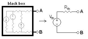
Any black box containing resistances only and voltage and current sources can be replaced to a Thévenin equivalent circuit consisting of an equivalent voltage source in series connection with an equivalent resistance.
To calculate the equivalent circuit:
- Calculate the output voltage, VAB, when in open circuit condition (no load resistor—meaning infinite resistance). This is VTh.
- Calculate the output current, IAB, when the output terminals are short circuited (load resistance is 0). RTh equals VTh divided by this IAB.
The equivalent circuit is a voltage source with voltage VTh in series with a resistance RTh.
Step 2 could also be thought of as:
- a. Replace the independent voltage sources with short circuits, and independent current sources with open circuits.
- b. Calculate the resistance between terminals A and B. This is RTh.
Reciprocity theorem
the reciprocity theorem states that if an emf E in one branch of a reciprocal network produces a current I in another, then if the emf E is moved from the first to the second branch, it will cause the same current in the first branch, where the emf has been replaced by a short circuit.
Norton's theorem
- Any linear electrical network with voltage and current sources and only resistances can be replaced at terminals A-B by an equivalent current source INO in parallel connection with an equivalent resistance RNO.
- This equivalent current INO is the current obtained at terminals A-B of the network with terminals A-B short circuited.
- This equivalent resistance RNO is the resistance obtained at terminals A-B of the network with all its voltage sources short circuited and all its current sources open circuited.

circuit containing resistances only and voltage and current sources can be replaced by an equivalent circuit consisting of an equivalent current source in parallel connection with an equivalent resistance.
To find the equivalent,
- Find the Norton current INo. Calculate the output current, IAB, with a short circuit as the load (meaning 0 resistance between A and B). This is INo.
- Find the Norton resistance RNo. When there are no dependent sources (all current and voltage sources are independent), there are two methods of determining the Norton impedance RNo.
-
- Calculate the output voltage, VAB, when in open circuit condition (i.e., no load resistor – meaning infinite load resistance). RNo equals this VAB divided by INo.
Thursday, July 16, 2015
Circuits connected in Parallel
In a parallel circuit the voltage is the same for all elements and corresponding current is different.

hen expression for series component of resistor capacitor and inductor are given by
Resistors:
The current in each individual resistor is found by Ohm's law. Factoring out the voltage gives
 .
To find the total resistance of all components, add the reciprocals of the resistances  of each component and take the reciprocal of the sum. Total resistance will always be less than the value of the smallest resistance:
 .
For only two resistors, the unreciprocated expression is reasonably simple:

To find the current in a component with resistance , use Ohm's law again:
, use Ohm's law again: .
The components divide the current according to their reciprocal resistances, so, in the case of two resistors,
 .
electrical conductance  is reciprocal to resistance, the expression for total conductance of a parallel circuit of resistors reads:
 .
Inductors:
Inductors follow the same law, in that the total inductance of non-coupled inductors in parallel is equal to the reciprocal of the sum of the reciprocals of their individual inductances:

 .
If the inductors are situated in each other's magnetic fields, this approach is invalid due to mutual inductance. If the mutual inductance between two coils in parallel is M, the equivalent inductor is:

If 

Capacitors:
The total capacitance of capacitors in parallel is equal to the sum of their individual capacitances:

 .
Circuits connected in Series
In a series circuit the current is the same for all elements and corresponding voltage is different.

Then expression for series component of resistor capacitor and inductor are given by
Resistor:
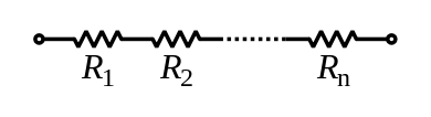
The total resistance of resistors in series is equal to the sum of their individual resistances:

Then expression for series component of resistor capacitor and inductor are given by
Resistor:
The total resistance of resistors in series is equal to the sum of their individual resistances:
Electrical conductance presents a reciprocal quantity to resistance. Total conductance of a series circuits of pure resistors, therefore, can be calculated from the following expression:
 .
For a special case of two resistors in series, the total conductance is equal to:

- Inductor:
- In that the total inductance of non-coupled inductors in series is equal to the sum of their individual inductances:


- it is difficult to prevent adjacent inductors from influencing each other, as the magnetic field of one device couples with the windings of its neighbours. This influence is defined by the mutual inductance M.
 .
For three coils, there are six mutual inductances ,
 ,
 and
 ,
 and
 . There are also the three self-inductances of the three coils:
 ,
 and
 .Therefore
 By reciprocity
 =
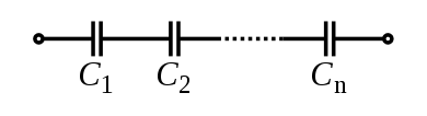
 Capacitor:The total capacitance of capacitors in series is equal to the reciprocal of the sum of the reciprocals of their individual capacitances:


Kirchhoff's laws
Kirchhoff's circuit laws:
This law is also called Kirchhoff's first law, Kirchhoff's point rule, or Kirchhoff's junction rule (or nodal rule).It implies that:
- At any node (junction) in an electrical circuit, the sum of currents flowing into that node is equal to the sum of currents flowing out of that node
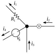
current entering any junction is equal to the current leaving that junction. i2 + i3 = i1 + i4
Kirchhoff's voltage laws:
This law is also called Kirchhoff's second law, Kirchhoff's loop (or mesh) rule, and Kirchhoff's second rule. It implies that
The directed sum of the electrical potential differences (voltage) around any closed network is zero, (or) the sum of the emfs in any closed loop is equivalent to the sum of the potential drops in that loop, (or)The algebraic sum of the products of the resistances of the conductors and the currents in them in a closed loop is equal to the total emf available in that loop.
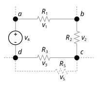
The sum of all the voltages around the loop is equal to zero.v1 + v2 + v3 - v4 = 0
superposition theorem
The superposition theorem for electrical circuits states that for a linear system the response (voltage or current) in any branch of a bilateral linear circuit having more than one independent source equals the algebraic sum of the responses caused by each independent source acting alone, where all the other independent sources are replaced by their internal impedances.
the contribution of each individual source, all of the other sources first must be set to zero by

the contribution of each individual source, all of the other sources first must be set to zero by
- Replacing all other independent voltage sources with a short circuit
- Replacing all other independent current sources with an open circuit
Suppose there are two voltage source s V1 and V2 acting simultaneously on the circuit.
Because of these two voltage sources, say current I flows through the resistance R.Now replace V2 by short circuit, keeping V1 at its position and measure current through the resistance, R. Say it is I1.Then replace, V1 by short circuit, reconnect V2 to its original position and measure current through the same resistance R and say it is I2.Now if we add these two currents, I1 and I2 we will get the current which is equal to the current - was actually flowing through R, when both voltage source s V1 and V2 were acting on the circuit simultaneously. That is I1 + I2 = I.
Wednesday, July 15, 2015
Different network theorem
1) kirchoff 's first and second law
2) Superposition theorem
3) Thevenin's theorem
4) Norton's theorem
5) reciprocity theorem
2) Superposition theorem
3) Thevenin's theorem
4) Norton's theorem
5) reciprocity theorem
Important related terms to Electric Circuits
Node
A point or junction where two or more circuit’s elements (resistor, capacitor, inductor etc) meet is called Node
Branch
That part or section of circuit which locate between two junctions is called branch
In branch, one or more elements can be connected and they have two terminals.
Loop
A closed path in circuit where more than two meshes can be occurred is called loop i.e. there may be many meshes in a loop, but a mesh does not contain on one loop.
Mesh
A closed loop which contains no other loop within it or a path which does not contain on other paths is called Mesh.
Subscribe to:
Posts (Atom)