Digital electronics are those electronics systems that use a digital signal instead of an analog signal. Digital electronics are the most common representation of Boolean algebra and are the basis of all digital circuits.In digital electronics all values are expressed in terms of 0's and 1's combination.
Tuesday, September 1, 2015
Thursday, July 23, 2015
working of amplifier
Single Stage RC Coupled CE Amplifier
The figure shows a single stage CE amplifier. C1 and C3 are coupling capacitors, they are used for blocking the dc component and passing only ac part they also ensure that the dc basing conditions of the BJT remains unchanged even after input is applied. C2 is the bypass capacitor which increases the voltage gain and bypasses the R4 resistor for ac signals. The BJT is biased in the active region using the necessary biasing components. The Q point is made stable in the active region of the transistor. When input is applied as shown below the base current starts to vary up and down, hence collector current also varies as IC = β × IB. Therefore voltage across R3 varies as the collector current is passing through it. Voltage across R3 is the amplified one and is 180° apart from the input signal. Thus voltage across R3 is coupled to the load and amplification has taken place. If the Q point is maintained to be at the centre of the load very less or no waveform distortion will take place. The voltage as well as current gain of the CE amplifier is high (gain is the factor by which the voltage of current increases from input to output). It is commonly used in radios and as low frequency voltage amplifier.
To further increase the gain multistage amplifiers are used. They are connected via capacitor, electrical transformer, R-L or directly coupled depending on the application. The overall gain is the product of gains of individual stages. Figure below shows a two stage CE amplifier. various parameters of CE amplifier are
| Definition | Expression (with emitter degeneration) | Expression (without emitter degeneration, i.e., RE = 0) | |
|---|---|---|---|
| Current gain |  |  |  |
| Voltage gain |  | 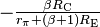 |  |
| Input impedance |  | 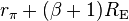 |  |
| Output impedance |  |  |  |
types of transistor amplifier
1. common Emitter amplifier
2. common Base amplifier
3. common Collector amplifier
2. common Base amplifier
3. common Collector amplifier
COMMON-COLLECTOR CONFIGURATION
COMMON-BASE CONFIGURATION
COMMON-EMITTER CONFIGURATION
Advantages and Disadvantages of transistor amplifier
Advantages of CE amplifier:
- A common emitter amplifier is inverting and has low input impedance
- high output impedance
- high voltage gain
- high current gain.
Disadvantages of CE amplifier:
- 1. It has a high output resistance.
- 2. It responds poorly to high frequencies.
- 3. It has high thermal instabilities.
- 4. It's voltage gain is very unstable.
Advantages of CB amplifier:
- decent voltage amplifier, and current in is about equal to current out (actually current in is slightly greater than current out).
- The common base circuit works best as a current buffer. It can take an input current at a low input impedance, and deliver nearly that same current to a higher impedance output.
Disadvantages of CB amplifier:
- It requires two DC power sources to run this type of circuit.
- Measure another voltage between emitter (input) and Collector(output).
- Compare voltage between Emitter and Base to see it is within the limit of transistor.
- Common Base circuit mostly use on OSC circuit or matching circuit. It has less gain than CE type.
- amplification factor of common base amplifier is less less than common emitter amplifier.
Advantages of CC amplifier:
- It has current gain but maintain voltage gain unchanged
- It has the lowest output impedance compare to other type amplifier
- It can be used for impedance matching between an amplifier stage with a high output impedance and an amplifier stage with a low input impedance.
- When used like this it is sometimes called a buffer amp or isolation amp.
- When placed between the the two stages it prevents the stage with the low input impedance from overloading the stage with the high output impedance.
- The Voltage gain of a common collector amp is at best slightly less than 1
COMPARISON AMONG DIFFERENT TYPES OF AMPLIFIER:
| Common Emitter | Common Collector | Common Base | |
|---|---|---|---|
| Voltage Gain | Medium | Low | High |
| Current Gain | Medium | High | Low |
| Input Impedance | Medium | High | Low |
| Output Impedance | Medium | Low | High |
Sunday, July 19, 2015

Application of network theorem
- Both the methods are used to solve the complex network.
- Norton's Theorem & Thevenin's Theorem are "Duals".
- substitution theorem can be used in both linear and nonlinear circuits. For those nonlinear circuits that have a unique solution, we can use the substitution theorem in the equivalent transformation.
- they can be applied to both ac and dc source.
- For easy detemination of circuit parameter
Conversion between thevienin circuit to norton circuit
A Norton equivalent circuit is related to the Thevenin equivalent by the following:


Thevenin's theorem
- Any linear electrical network with voltage and current sources and only resistances can be replaced at terminals A-B by an equivalent voltage source Vth in series connection with an equivalent resistance Rth.
- This equivalent voltage Vth is the voltage obtained at terminals A-B of the network with terminals A-Bopen circuited.
- This equivalent resistance Rth is the resistance obtained at terminals A-B of the network with all its independent current sources open circuited and all its independent voltage sources short circuited.
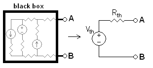
Any black box containing resistances only and voltage and current sources can be replaced to a Thévenin equivalent circuit consisting of an equivalent voltage source in series connection with an equivalent resistance.
To calculate the equivalent circuit:
- Calculate the output voltage, VAB, when in open circuit condition (no load resistor—meaning infinite resistance). This is VTh.
- Calculate the output current, IAB, when the output terminals are short circuited (load resistance is 0). RTh equals VTh divided by this IAB.
The equivalent circuit is a voltage source with voltage VTh in series with a resistance RTh.
Step 2 could also be thought of as:
- a. Replace the independent voltage sources with short circuits, and independent current sources with open circuits.
- b. Calculate the resistance between terminals A and B. This is RTh.
Reciprocity theorem
the reciprocity theorem states that if an emf E in one branch of a reciprocal network produces a current I in another, then if the emf E is moved from the first to the second branch, it will cause the same current in the first branch, where the emf has been replaced by a short circuit.
Norton's theorem
- Any linear electrical network with voltage and current sources and only resistances can be replaced at terminals A-B by an equivalent current source INO in parallel connection with an equivalent resistance RNO.
- This equivalent current INO is the current obtained at terminals A-B of the network with terminals A-B short circuited.
- This equivalent resistance RNO is the resistance obtained at terminals A-B of the network with all its voltage sources short circuited and all its current sources open circuited.

circuit containing resistances only and voltage and current sources can be replaced by an equivalent circuit consisting of an equivalent current source in parallel connection with an equivalent resistance.
To find the equivalent,
- Find the Norton current INo. Calculate the output current, IAB, with a short circuit as the load (meaning 0 resistance between A and B). This is INo.
- Find the Norton resistance RNo. When there are no dependent sources (all current and voltage sources are independent), there are two methods of determining the Norton impedance RNo.
-
- Calculate the output voltage, VAB, when in open circuit condition (i.e., no load resistor – meaning infinite load resistance). RNo equals this VAB divided by INo.
Thursday, July 16, 2015
Circuits connected in Parallel
In a parallel circuit the voltage is the same for all elements and corresponding current is different.

hen expression for series component of resistor capacitor and inductor are given by
Resistors:
The current in each individual resistor is found by Ohm's law. Factoring out the voltage gives
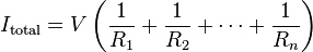 .
.
To find the total resistance of all components, add the reciprocals of the resistances  of each component and take the reciprocal of the sum. Total resistance will always be less than the value of the smallest resistance:
of each component and take the reciprocal of the sum. Total resistance will always be less than the value of the smallest resistance:
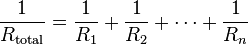 .
.
For only two resistors, the unreciprocated expression is reasonably simple:

To find the current in a component with resistance , use Ohm's law again:
, use Ohm's law again: .
.
The components divide the current according to their reciprocal resistances, so, in the case of two resistors,
 .
.
electrical conductance  is reciprocal to resistance, the expression for total conductance of a parallel circuit of resistors reads:
is reciprocal to resistance, the expression for total conductance of a parallel circuit of resistors reads: .
.
Inductors:
Inductors follow the same law, in that the total inductance of non-coupled inductors in parallel is equal to the reciprocal of the sum of the reciprocals of their individual inductances:

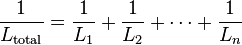 .
.
If the inductors are situated in each other's magnetic fields, this approach is invalid due to mutual inductance. If the mutual inductance between two coils in parallel is M, the equivalent inductor is:

If 

Capacitors:
The total capacitance of capacitors in parallel is equal to the sum of their individual capacitances:

 .
.
Circuits connected in Series
In a series circuit the current is the same for all elements and corresponding voltage is different.

Then expression for series component of resistor capacitor and inductor are given by
Resistor:
The total resistance of resistors in series is equal to the sum of their individual resistances:


Then expression for series component of resistor capacitor and inductor are given by
Resistor:
The total resistance of resistors in series is equal to the sum of their individual resistances:
Electrical conductance presents a reciprocal quantity to resistance. Total conductance of a series circuits of pure resistors, therefore, can be calculated from the following expression:
 .
.
For a special case of two resistors in series, the total conductance is equal to:

- Inductor:
- In that the total inductance of non-coupled inductors in series is equal to the sum of their individual inductances:


- it is difficult to prevent adjacent inductors from influencing each other, as the magnetic field of one device couples with the windings of its neighbours. This influence is defined by the mutual inductance M.
 .
.
For three coils, there are six mutual inductances ,
,  ,
,  and
and  ,
,  and
and  . There are also the three self-inductances of the three coils:
  ,
,  and
and  .Therefore
 By reciprocity
 =
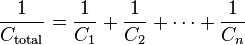
=  Capacitor:The total capacitance of capacitors in series is equal to the reciprocal of the sum of the reciprocals of their individual capacitances:


Subscribe to:
Posts (Atom)