Thursday, July 16, 2015

Kirchhoff's laws


Kirchhoff's circuit laws:
This law is also called Kirchhoff's first law, Kirchhoff's point rule, or Kirchhoff's junction rule (or nodal rule).It implies that:
At any node (junction) in an electrical circuit, the sum of currents flowing into that node is equal to the sum of currents flowing out of that node                                              
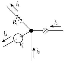
                                                             
 current entering any junction is equal to the current leaving that junction. i2 + i3 = i1 + i4

Kirchhoff's voltage laws:
This law is also called Kirchhoff's second law, Kirchhoff's loop (or mesh) rule, and Kirchhoff's second rule. It implies that 
The directed sum of the electrical potential differences (voltage) around any closed network is zero, (or) the sum of the emfs in any closed loop is equivalent to the sum of the potential drops in that loop, (or)The algebraic sum of the products of the resistances of the conductors and the currents in them in a closed loop is equal to the total emf available in that loop.
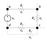
                                                          
The sum of all the voltages around the loop is equal to zero.v1 + v2 + v3 - v4 = 0


superposition theorem

The superposition theorem for electrical circuits states that for a linear system the response (voltage or current) in any branch of a bilateral linear circuit having more than one independent source equals the algebraic sum of the responses caused by each independent source acting alone, where all the other independent sources are replaced by their internal impedances. 

the contribution of each individual source, all of the other sources first must be set to zero by

       superposition 1
Suppose there are two voltage source s V1 and V2 acting simultaneously on the circuit. Because of these two voltage sources, say current I flows through the resistance R.Now replace V2 by short circuit, keeping V1 at its position and measure current through the resistance, R. Say it is I1.Then replace, V1 by short circuit, reconnect V2 to its original position and measure current through the same resistance R and say it is I2.Now if we add these two currents, I1 and I2 we will get the current which is equal to the current - was actually flowing through R, when both voltage source s V1 and V2 were acting on the circuit simultaneously. That is I1 + I2 = I.

Wednesday, July 15, 2015

Different network theorem

1) kirchoff 's first and second law
2) Superposition theorem
3) Thevenin's theorem
4) Norton's theorem
5) reciprocity theorem

Important related terms to Electric Circuits

Node
A point or junction where two or more circuit’s elements (resistor, capacitor, inductor etc) meet is called Node
Branch
That part or section of circuit which locate between two junctions is called branch
In branch, one or more elements can be connected and they have two terminals.
Loop
A closed path in circuit where more than two meshes can be occurred is called loop i.e. there may be many meshes in a loop, but a mesh does not contain on one loop.
Mesh
A closed loop which contains no other loop within it or a path which does not contain on other paths is called Mesh.

transistor working principle

The design of a transistor allows it to function as an amplifier or a switch. This is accomplished by using a small amount of electricity to control a gate on a much larger supply of electricity, much like turning a valve to control a supply of water. Transistors are composed of three 
parts – a base, a collector, and an emitter. The base is the gate controller device for the larger electrical supply. The collector is the larger electrical supply, and the eitter ism the outlet for that supply. By sending varying levels of current from the base, the amount of current flowing through the gate from the collector may be regulated. In this way, a very small amount of current may be used to control a large amount of current, as in an amplifier. The same process is used to create the binary code for the digital processors but in this case a voltage threshold of five volts is needed to open the collector gate. In this way, the transistor is being used as a switch with a binary function: five volts – ON, less than five volts – OFF. 

Transistor as a Switch

One of the most common uses for transistors in an electronic circuit is as simple switches. In short, a transistor conducts current across the collector-emitter path only when a voltage is applied to the base. When no base voltage is present, the switch is off. When base voltage is present, the switch is on.
In an ideal switch, the transistor should be in only one of two states: off or on. The transistor is off when there's no bias voltage or when the bias voltage is less than 0.7 V. The switch is on when the base is saturated so that collector current can flow without restriction.

Transistor Regions of Operation

A transistor can be operated in three different regions as
  • active region
  • saturation region
  • cut-off region

active region:
The transistor is said to be operated in active region when the emitter-base junction is forward biased and collector –base junction is reverse biased. The collector current is said to have two current components one is due to the forward biasing of EB junction and the other is due to reverse biasing of CB junction. The collector current component due to the reverse biasing of the collector junction is called reverse saturation current (ICO or ICBO) and it is very small in magnitude.

Saturation region:
Transistor is said to be operated in saturation region when both EB junction and CB junction are forward biased as shown. When transistor is operated in saturation region IC increases rapidly for a very small change in VC.

Cut-off region:
When both EB junction and CB junction are reverse biased, the transistor is said to be operated in cut-off region. In this region, the current in the transistor is very small and thus when a transistor in this region it is assumed to be in off state.